top of page

AX Molding Co., Ltd.
Specialized manufacturer of T-dies and feed blocks
We can handle a variety of applications, including high-precision thin film dies, sheet dies, and multi-layered products.

Feedblock
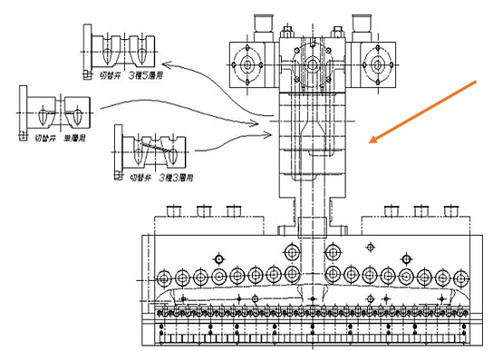
Multilayer feedblock method: This method combines resins before the single manifold die. A feature of the feedblock is that it can produce a variety of films and sheets by switching the switch valve, such as two-type three-layer, three-type three-layer, three-type five-layer, or single-layer. However, because the resin flow paths are complex within a single block, there is a risk of some buildup. The resin inlet of the T-die must be the same as the feedblock outlet, such as an oval or square, and a separate T-die for the feedblock is required. The switch valve easily changes the position of each layer. It is also possible to split a single layer's resin flow path into two, taking into account buildup and other factors, allowing the resin to flow into a non-resin flow path and merge. The thickness of each layer is adjusted by the extrusion rate or a straightening pin. Feedblocks include vane types (which adjust the thickness of each layer by changing the angle of the vanes) and stacked block types.
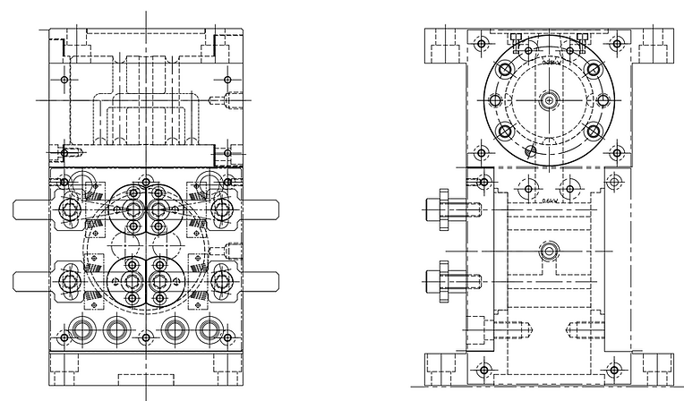
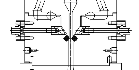
Standard feedblock shape (reference image)


Standard feedblock shape (reference diagram)
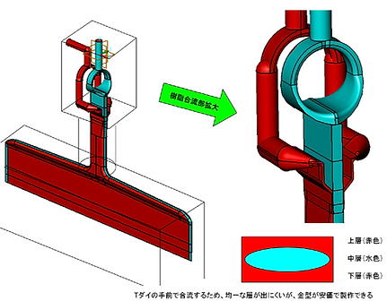
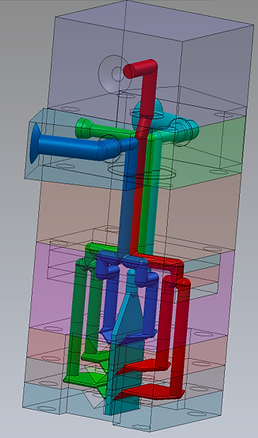
<Flow path modeling image>


フィードブロック方式の多層フィルム成形
Feedblock method multilayer film molding has the following advantages:
・The cartridge system allows for the replacement of each resin layer in a short time. ・The flow path is not split in half even when disassembled, so the internal parts are less likely to be damaged and disassembly and cleaning are easy. ・It can be manufactured more cheaply than a multi-manifold. ・It is more compact than a T-die and is easier to handle. It can be attached to a dedicated T-die for a feed block, regardless of lip width (the inlet should be aligned with the oval outlet of the feed block).
<Disadvantages>
・The thickness ratio of each resin cannot be precisely controlled. If there is a large difference in viscosity between the resins, the flow path after they join will be long, resulting in variations in the thickness ratio. ・Many blocks are combined in a complex manner, resulting in frequent resin leakage. ・The resin flows around the outside of the cartridge and joins not only where the resins join, but also in other locations, causing defects in the film product. ・Since the flow paths are often square rather than round, resin accumulates in the corners. It can be difficult to apply chrome plating to flow paths (this can also be the case with Kanigen plating).
The following characteristics are mentioned,
We have adopted a design method that takes advantage of the advantages while minimizing the disadvantages as much as possible.
<Various FB reference photos>


Block stacking feedblock
In the laminated FB, raw materials supplied from the extruder to the feed block are branched within the feed block using laminated blocks (e.g., dividing three types of raw materials into five layers). Since the laminated blocks have flow paths tightly attached to each other on flat surfaces, it is necessary to design them taking into consideration the surface pressure of the sealing surfaces to prevent resin leakage. This is packed with know-how, such as bolt placement and counterbore of the sealing surfaces.


Diversion section (laminated block
Confluence (stacked blocks

In the case of laminated FB, there is a type that has a thin T-die type joining section at the joining point.
The layer ratio of each layer can be changed by bending the flow path dimensions at the confluence.
Wrapping can also be prevented by bending the junction. Our know-how in feed blocks is unique to our company.
Cartridge type + stackable block feedblock

Diversion section (cartridge)
Confluence (stacked blocks)
<Cartridge-equipped + vane-type feed block>
Diversion section (cartridge)
Confluence Bane

Adjust the flow path width with vanes

Adjustment pin
scale
handle
By using bending vanes and bending beaks, the envelopment of the central layer is reduced.
We have the know-how to control the film thickness in the center.
<Feed block with choke bar>
Outer layer choke bar method. If the viscosity of the resin or the extrusion volume changes, the flow in the flow path of the T-die shape will also change. In order to align the flow, there is a method that uses a choke bar. The choke bar does not move as a whole, but has grooves carved into it, allowing it to move flexibly. This method is effective for adjusting when placing the outer layer on the main layer.

When the exterior material is changed to a different type of film, the viscosity and flow rate will naturally change. This can be adjusted by adjusting the gap in the flow path with this choke bar, which changes the flow of resin.
The choke bar can be adjusted while attached to the equipment without disassembling the T-die feed block.
The structure allows for fine adjustments at the production conditions stage.


By tightening and retracting this adjustment bolt, the clearance of the flow path can be adjusted.


<Choke bar + Feed block with flow control pin>

Confluence section


Chalk Bar
Flow Control Pin
A method in which the confluence of the flow control pin is processed to allow for various adjustments to the flow channel gap (this can be adjusted during testing for each resin, allowing the final flow channel shape to be considered).
"Ultra-compact multi-layer feedblock"
The secret to its compact size is this FB. It measures just L 70 x W 70 x H 70 (mm), and is a layer-switching cartridge type.


<Super multilayer feedblock>

<Multi-pliers type feed block>


By creating a multiplier channel inside the feedblock, it is possible to produce ultra-multilayer films.
We also accept orders for the production of ultra-multilayer feed blocks using existing T-dies.
As in the example above, we take advantage of the advantages of feed blocks while using our experience and design capabilities to address areas where disadvantages may arise, thereby resolving any problems you may have.
Example: We installed our new feed block to the customer's existing multi-layer extruder and existing T-die to stabilize the layer ratio.
New parts were installed (modified) on the existing feed block to stabilize the layer ratio.
Create a new switching cartridge and change the layer configuration of an existing feedblock
We also have a wealth of knowledge about feed blocks.
bottom of page